
Grooved Pins & Studs
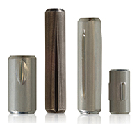
Grooved pins are non-threaded press fit fasteners — a fastener that is pressed into an appropriate sized hole, providing the proper interference fit to lock the fastener in place.
- Commonly used as locking devices, pivots, bearing faces or locating elements where there is not a high degree of end load
- Available with many different groove types
- Typically zinc-plated, made from unhardened, low-carbon steel – but available in a wide range of finishes and heat treatments for shear resistance
- Wide range of diameters, lengths and end configurations available
Shortest Lead Times on Custom Grooved Pins: How and When You Need Them
Driv-Lok is known for short lead times on custom pins. We haven’t settled on just having the shortest lead time, we continuously look to improve on lead time because in today’s competitive environment, it’s all about time and every day counts.
We know that customers need to be flexible and respond to their demanding environments to be successful. Need Driv-Lok Grooved Pins in standard sizes immediately? We have partnered with Stocking Distributors that have immediate delivery.
Description
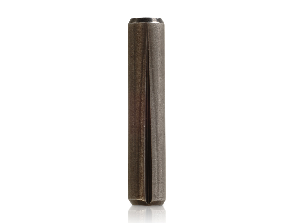
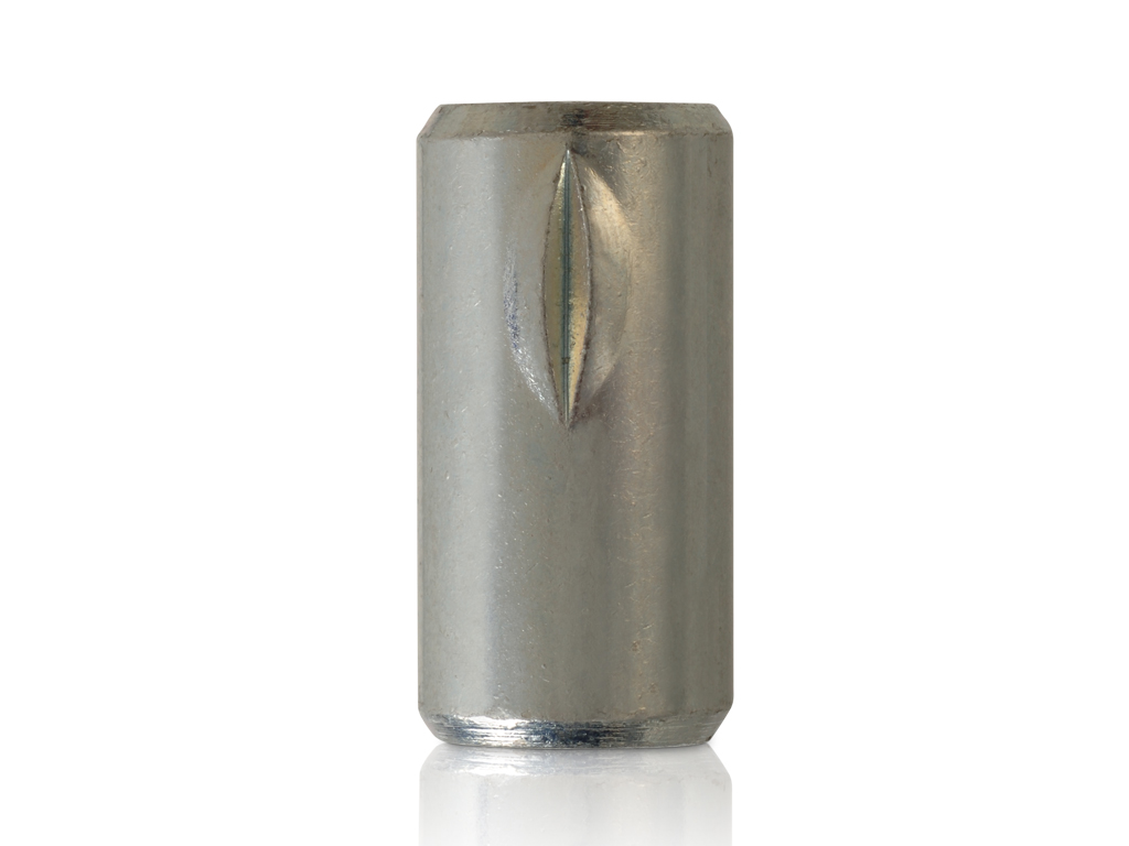
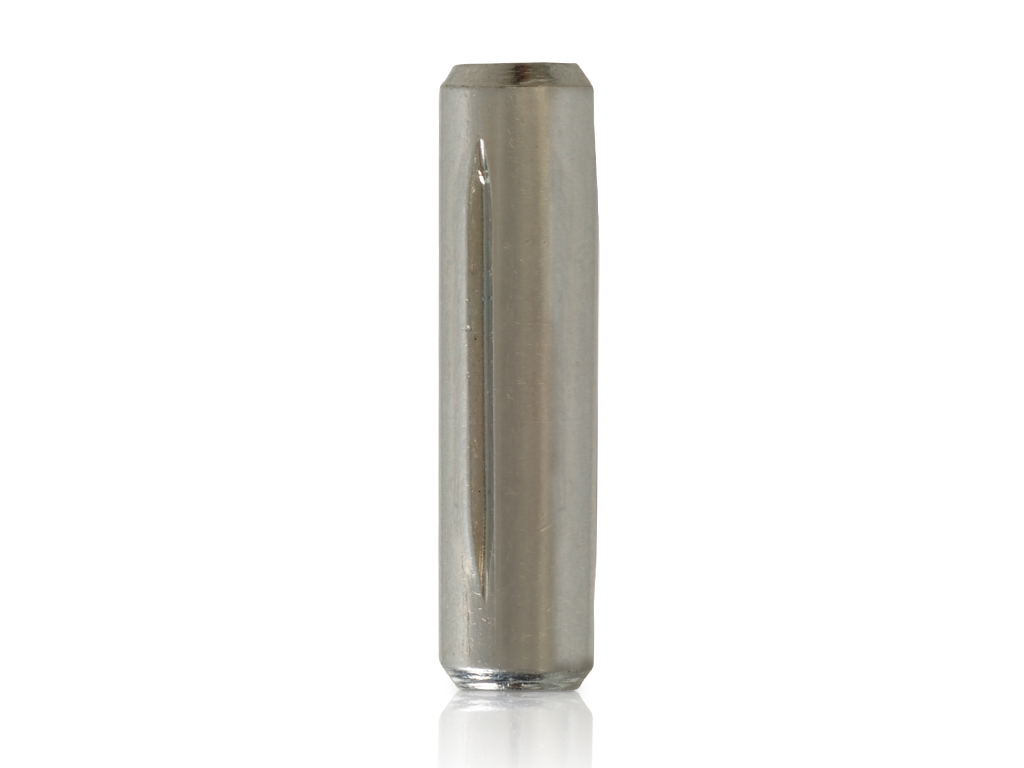
The crest of these raised portions forms the expanded diameter or “Dx” dimension which is shown in Figure 1. The Dx is a few thousandths larger than the nominal diameter “D” of the pin. The amount of expansion varies with the diameter of the pin, the material being grooved, and the style of groove.
Function
When a grooved pin is used, the hole into which the pin is to be inserted is drilled a few thousandths larger than the nominal diameter of the pin. The hole must never be smaller than the nominal diameter of the pin. (See Grooved Pin Drilling Procedures and Hole Tolerances on page 4.)When the expanded portion of the pin is compressed by insertion into the hole, radial holding forces are generated as shown in Figure 2. These radial forces lock the pin securely into the drilled hole.
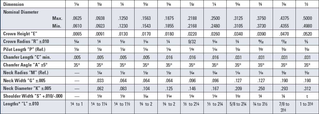
Dimensions

CAD Diagram
Success stories
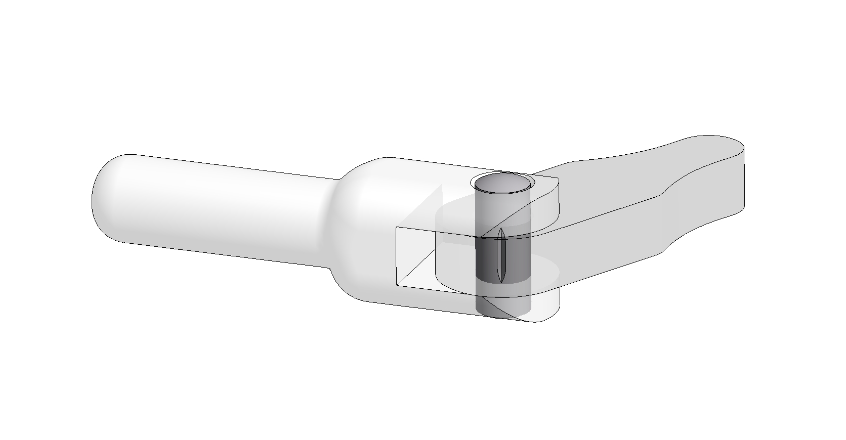
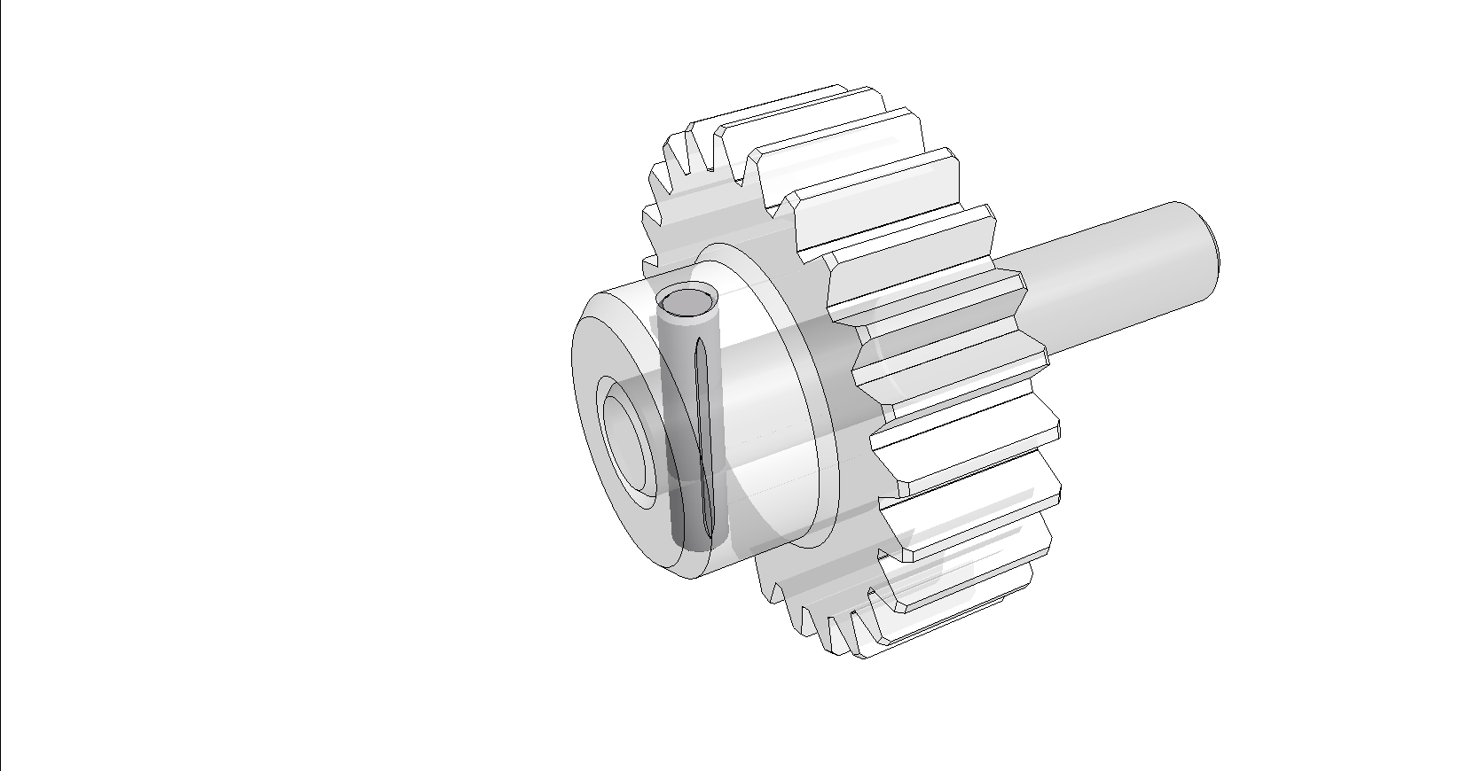
SITUATION
A heavy equipment manufacturer using a threaded fastener was experiencing loosening of the joint due to vibration in a hinged joint application. in addition, their current assembly method was extremely slow and ineffi cient.
SOLUTION
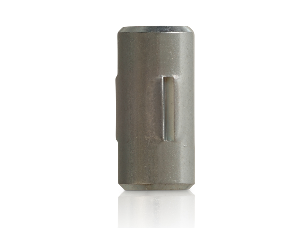
The Driv-Lok Inc. ENGINOMICS ® team introduced a Type “E” Groove Pin to the design. This pin eliminateD the loosening that the threaded fastener experienced. The team also designed an insertion press to install the pin. This press holds multiple pieces in place, hands free, while the pin is inserted into the application. The design
is such that the pin is installed to the same depth every time. The end result was a complete system to solve both the fastening and installation problems.
ADVANTAGES
- HIGHLY EFFICIENT, HANDS-FREE ASSEMBLY METHOD
- COST EFFECTIVE ASSEMBLY FUNCTION
- LOWER INSTALLATION COSTS
- ONE SOURCE FOR FASTENERS AND INSTALLATION
![]()
![]()
Grooved pin diameter / shaft size /
torque relationships.
This table is a guide in selecting the proper-size DRIV-LOK Grooved Pin to use for fastening machine members to shafts of given sizes and for specific load requirements. Torque and horsepower ratings are based on pins made of cold finished, low carbon steel and a safety factor of 8 is assumed.
|
Recommended pin diameter for various shaft sizes |
|||
|
Shaft size |
Pin diameter |
Torque inch lbs. |
H.P. at 100 R.P.M. |
|
3/16 |
1/16 |
4.8 |
.007 |
|
7/32 |
5/64 |
8.5 |
.013 |
|
1/4 |
3/32 |
13.9 |
.022 |
|
5/16 |
7/64 |
23.8 |
.038 |
|
3/8 |
1/8 |
37.5 |
.060 |
|
7/16 |
5/32 |
62.9 |
.100 |
|
1/2 |
5/32 |
71.9 |
.114 |
|
9/16 |
3/16 |
116.4 |
.185 |
|
11/16 |
7/32 |
193.8 |
.307 |
|
3/4 |
1/4 |
275.6 |
.437 |
|
13/16 |
1/4 |
298.6 |
.474 |
|
7/8 |
1/4 |
322 |
.510 |
|
15/16 |
15/16 |
449 |
.712 |
|
1 |
15/16 |
479 |
.759 |
|
1 1/16 |
15/16 |
509 |
.807 |
|
1 1/8 |
3/8 |
773 |
1.23 |
|
1 3/16 |
3/8 |
816 |
1.30 |
|
1 1/4 |
3/8 |
859 |
1.36 |
|
1 5/16 |
7/16 |
1230 |
1.95 |
|
1 3/8 |
7/16 |
1289 |
2.05 |
|
1 7/16 |
7/16 |
1348 |
2.14 |
|
1 1/2 |
1/2 |
1838 |
2.92 |
Minimum double shear values (lbs.) of Driv-Lok pins of various
|
|
Grooved pins |
Slotted spring pins |
|||
|
Pin diameter |
Low carbon |
Shear-proof alloy steel (RC 40-48) |
Corrosion resistant steel |
Brass |
1074 steel |
|
1/16 |
410 |
720 |
540 |
250 |
430 |
|
3/32 |
890 |
1,600 |
1,240 |
560 |
1,150 |
|
1/8 |
1,600 |
2,820 |
2,200 |
990 |
1,875 |
|
5/32 |
2,300 |
4,520 |
3,310 |
1,540 |
2,750 |
|
3/16 |
3,310 |
6,400 |
4,760 |
2,200 |
4,150 |
|
7/32 |
4,510 |
8,770 |
6,480 |
3,020 |
5,850 |
|
1/4 |
5,880 |
11,500 |
8,460 |
3,950 |
7,050 |
|
5/16 |
7,660 |
17,900 |
12,700 |
6,170 |
10,800 |
|
3/8 |
11,000 |
26,000 |
18,200 |
9,050 |
16,300 |
|
7/16 |
15,000 |
35,200 |
24,800 |
12,100 |
19,800 |
|
1/2 |
19,600 |
46,000 |
32,400 |
15,800 |
27,100 |